RF Generator
The Nanonis RF generator is a compact, low phase noise RF signal generator. It is designed for applications requiring CW or pulsed RF and MW signals over a very large range of frequencies or requiring a very low phase-noise RF signal source. The large frequency range up to 40 GHz makes it particularly suited for ESR/EPR experiments or as a local oscillator for quantum computing applications.
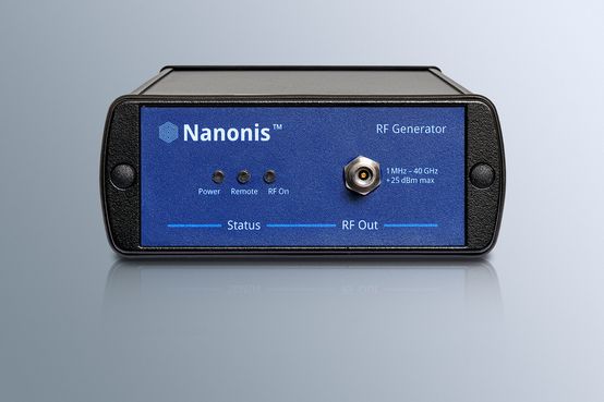
The Nanonis RF Generator is a very compact instrument, and that allows a placement very close to the sample or cryostat feedthrough. A multiple local oscillator set-up with several RF generators requires only limited space. Since the RF generator is passively cooled and uses an external power supply, it can be placed directly on experimental set-ups sensitive to vibrations like scanning tunneling microscopes.
The Nanonis RF Generator features an 2.92 mm RF output supporting a frequency range from 1 MHz to 40 GHz and with a power range of -20 dBm to more than +15 dBm (depending on frequency) and a switching time of 500 µs. It offers very low phase noise, for example less than -120 dBc/Hz at 20 GHz with 10 kHz offset.
The generator’s trigger port can alternatively be used for pulse modulation, offering a cost-effective solution for pulsed experiments. An external clock source of 100 MHz or 1 GHz can be used as a reference clock. The instrument also outputs its reference clock signal (generated by an internal OCXO) on a clock-output connector allowing multiple units to output phase-coherent signals.
When purchased in combination with or for a Nanonis System, the instrument is tightly integrated into the Nanonis software. The Nanonis RF Generator can be clocked from a 100 MHz master clock generated by the RC5e reducing trigger uncertainty. All parameters can be used as measurement variables, real-time measurements are possible through triggering. A trigger-engine allows fast pulse modulation measurements with low trigger uncertainty eliminating the need for an AWG for time resolutions above 10 ns.
SPECIFICATIONS
| RF output | - |
| Output connector | 1x 2.92 mm K-type female |
| Output coupling | AC |
| Output impedance | 50 Ω |
| Frequency range | 1 MHz to 40 GHz |
| Frequency Resolution | 0.001 Hz |
| Phase Resolution | 0.1 degrees |
| Switching speed | 500 µs |
| Output power level | -10 dBm to +21 dBm (1 MHz – 1 GHz) -10 dBm to +22 dBm (1 GHz – 18 GHz) -10 dBm to +18 dBm (18 GHz – 23 GHz) -20 dBm to +16 dBm (23 GHz – 32 GHz) -20 dBm to +12 dBm (32 GHz - 40 GHz) |
| Output power level uncertainty | ±0.5 dBm typ. ±1.0 dBm max. (1 MHz – 15 GHz) ±0.75 dBm typ., ±1.0 dBm max (15 GHz – 23 GHz) ±1 dBm typ., ±1.5 dBm max (23 GHz – 35 GHz) ±1 dBm typ., ± 2.0 dBm max (35 GHz – 40 GHz) |
| Output power resolution | 0.5 dBm |
| Single sideband phase noise @ 1 GHz | -88 dBc/Hz typ. @ 10 Hz from carrier -131 dBc/Hz typ. @ 1 kHz from carrier -147 dBc/Hz typ. @ 100 kHz from carrier -154 dBc/Hz typ. @ 10 MHz from carrier |
| Single sideband phase noise @ 10 GHz | -67 dBc/Hz typ. @ 10 Hz from carrier -111 dBc/Hz typ. @ 1 kHz from carrier -127 dBc/Hz typ. @ 100 kHz from carrier -138 dBc/Hz typ. @ 10 MHz from carrier |
| Single sideband phase noise @ 30 GHz | -57 dBc/Hz typ. @ 10 Hz from carrier -102 dBc/Hz typ. @ 1 kHz from carrier -118 dBc/Hz typ. @ 100 kHz from carrier -129 dBc/Hz typ. @ 10 MHz from carrier |
| Harmonics (+10 dBm output power) | -30 dBc typ. (1 MHz – 1 GHz) -15 dBc typ. (1 GHz – 4 GHz) -25 dBc typ. (4 GHz – 7 GHz) -30 dBc typ. (7 GHz – 11 GHz) -25 dBc typ. (11 GHz – 20 GHz) -20 dBc typ. (20 GHz – 40 GHz) |
| Trigger input | - |
| Input connector | SMA female |
| High input level | +5 V |
| Trigger latency | 140 ns typ. |
| Trigger uncertainty | 20 ns typ. |
| User settable trigger delay | 0 to 20 s |
| Trigger delay resolution | 10 ns |
| Trigger type | Continuous, single, gated, gated direction |
| Trigger source | External, TCP/IP |
| Pulse modulation | - |
| Modulation source | Internal, External (trigger port) |
| Repetition frequency | DC to 10 MHz |
| Minimum pulse width | 30 ns |
| Maximum pulse width | 20 s |
| Pulse rise/fall time | 10 ns |
| Modulation on/off ratio (+10 dBm output power) | 60 dB typ. (1 MHz – 1 GHz) 40 dB typ. (1 GHz – 20 GHz) 45 dB typ. (20 GHz – 27 GHz) 55 dB typ. (27 GHz – 40 GHz) |
| Clock input | - |
| Input connector | SMA female |
| Input impedance | 50 Ω |
| Frequency | 100 MHz or 1 GHz |
| Waveform Type | Square |
| Clock output | - |
| Output connector | SMA female |
| Output impedance | 50 Ω |
| Frequency | 100 MHz or 1 GHz (only with 1 GHz external clock source) |
| Waveform Type | Square |
| Internal clock | - |
| Clock type | OCXO |
| Frequency | 100 MHz |
| Accuracy | ±30 ppb |
| Temperature Stability | ±100 ppb (0 to 50 °C) |
| Power Supply | - |
| Power Supply | External power supply included, power swithch on instrument |
| Power supply connector | DC Jack 5.5 mm x 2.1 mm PE (chassis) on shield |
| Power supply voltage | +24 V |
| power consumption | 26 W max incluing power supply losses 60 W rated power supply power |
| Dimensions | 10.8 x 32.0 x 4.2 cm (WxDxH) |
| Weight | Approx. 2.5 kg |